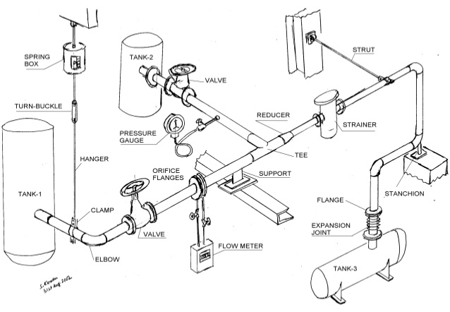

Bill of Material Section – List of the components for the portion of line shown in the isometric graphic.Main Graphic Section – A detailed orthographic representation that illustrates the details of 3D structure of the piping system in a single view.To accomplish this task, the piping isometric drawing consists of three sections that hold valuable info used by different project stakeholders at different times. The Isos bring clarity to contractors, construction crew and the overall project. It´s a three dimensional representation of a pipe line or part of it with all information necessary to purchase, fabricate, install and test the line or part of the line. Orifice meter taps orientation (it depends upon the pipe direction and fluid typeīOM section is a very important section, as it affects the cost of the project.For many decades Piping Isometric drawings have been used to represent a single pipe line in a plant, being the most important deliverable.Minimum gap requirement between the welds.Field weld and Workshop weld Identification.


Insulation and Heat Tracing Type (If the line is insulated only).Project Name, Project Code and Area Code.Here, you will learn to check the piping isometric drawing section-wise for ease of learning. The isometric drawing sheet consists of four major parts viz title block, drawing area, BOQ (Bill of Quantity ) section, and Special requirement notes section. To check the connection/end requirements for mounting the instruments. To check special items type and their dimensions To check elevation and orientation of connected nozzle

To check line route, dimension, elevation, valve orientation and co-ordinates To check Design Pressure & Temperature, stress critical lines, Hydro test pressure, inspection class and type, etc. To cross-check line number, line size, insulation, special requirement notes (like no pocket, press head), etc. P&ID (Piping and Instrumentation Diagram) Documents Required for Checking Piping Isometric Drawing Documents


 0 kommentar(er)
